


Raytool Cutting Head Focus Adjustment
Laser Cutting Quality Advisory Raytool Cutting Head– Moon Machinery Inc.
Please note that the cutting quality of your laser system is primarily influenced by four key factors:
-
Cutting Parameters – Ensure correct settings for speed, power, frequency, and focus height.
-
Cutting Nozzle Quality – A damaged or worn nozzle can significantly impact cut precision and consistency.
-
Protective Lens Condition – Contaminated or scratched protective lenses will interfere with beam transmission.
-
Cutting Gas Pressure – Inadequate or unstable gas pressure can lead to poor edge quality and dross formation.
If you have thoroughly verified all the above and are still experiencing subpar cutting results—especially when using a Raytools cutting head—we recommend checking the laser focus alignment.
We’ve prepared a short video guide to help you inspect and correct the laser focus. This can often resolve quality issues that persist after other adjustments.
For additional assistance, please don’t hesitate to contact us here.

How to adjust the focus of raytool laser head

Safety Instructions for the Raytool Cutting Head Focus Adjustment
- Before using the Raytool Cutting Head, personnel must have studied the relevant regulations and safety instructions and understand the possible hazards.
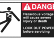
- Comply with relevant regulations and implement corresponding protective measures when operating or maintaining the Raytool Cutting Head. Safety Instructions Prevent Electric Shock
- Certain parts of the Raytool Cutting Head—such as the nozzle, sensor, sensor interface, and attached fasteners—may not be fully protected by the ground wire due to function fault. These parts may have low voltage.
- When installing or servicing electrical equipment connected to the Raytool Cutting Head, please pay attention to taking anti electric shock measures for relevant personnel.
- Note that the equipment shall be grounded as specified. Guard against Danger
- Never put your hands or other body parts inside the activated machine while the Raytool Cutting Head is active.
Tips for the Raytool Cutting Head Focus Adjustment
Knowing more about your laser cutting head does not hurt
- Advanced Options
- Apply MicroJoint to selected graphic: modify the MicroJoint size of the selected graphic and change all the selected graphics into the same size.
- Joint at Start: select to add one micro joint at the start point. Joint by Flycut: select to add one micro joint in fly cutting.
- Add Leadline at micro joint: select to add a leadline at micro joint.
- Deselect, the leadline can only be added after
exploding microjoint.
- Corner Parameter
- Micro Joint avoid corner: select to use the function.
- Safety distance: the determination range of corners.
- Maximum angle: the determination angle of corners.
- Take the parameters in the figure above as an example: the corner whose angle is less than 180° will not be added the micro joint, including the distance near it for 5mm, though the corner fits the conditions.
- Range
- Min MicroJoint curve
Conclusion
Achieving optimal laser cutting quality—especially when using the Raytool Cutting Head—requires close attention to several key factors. Cutting parameters such as speed, power, frequency, and focus height must be properly set. The condition of the cutting nozzle and protective lens also plays a crucial role, as damage or contamination can greatly reduce performance. Ensuring correct gas pressure is equally important to avoid dross and maintain clean edges.
Operators must follow all safety guidelines when working with the Raytool Cutting Head. Low-voltage risks from components like the sensor or nozzle emphasize the need for proper grounding and anti-electric shock precautions. Never reach into the machine while it is active, and always prioritize safe operation.
For more advanced control, features like MicroJoint adjustments and corner parameters can improve cut precision. If all settings have been verified and issues persist, we strongly recommend checking laser focus alignment. A short video guide is available to assist with this process.